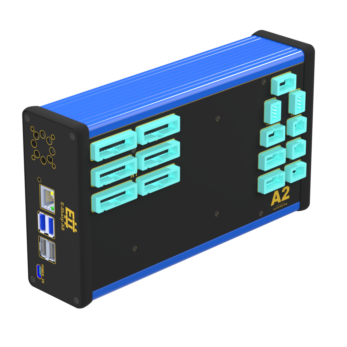
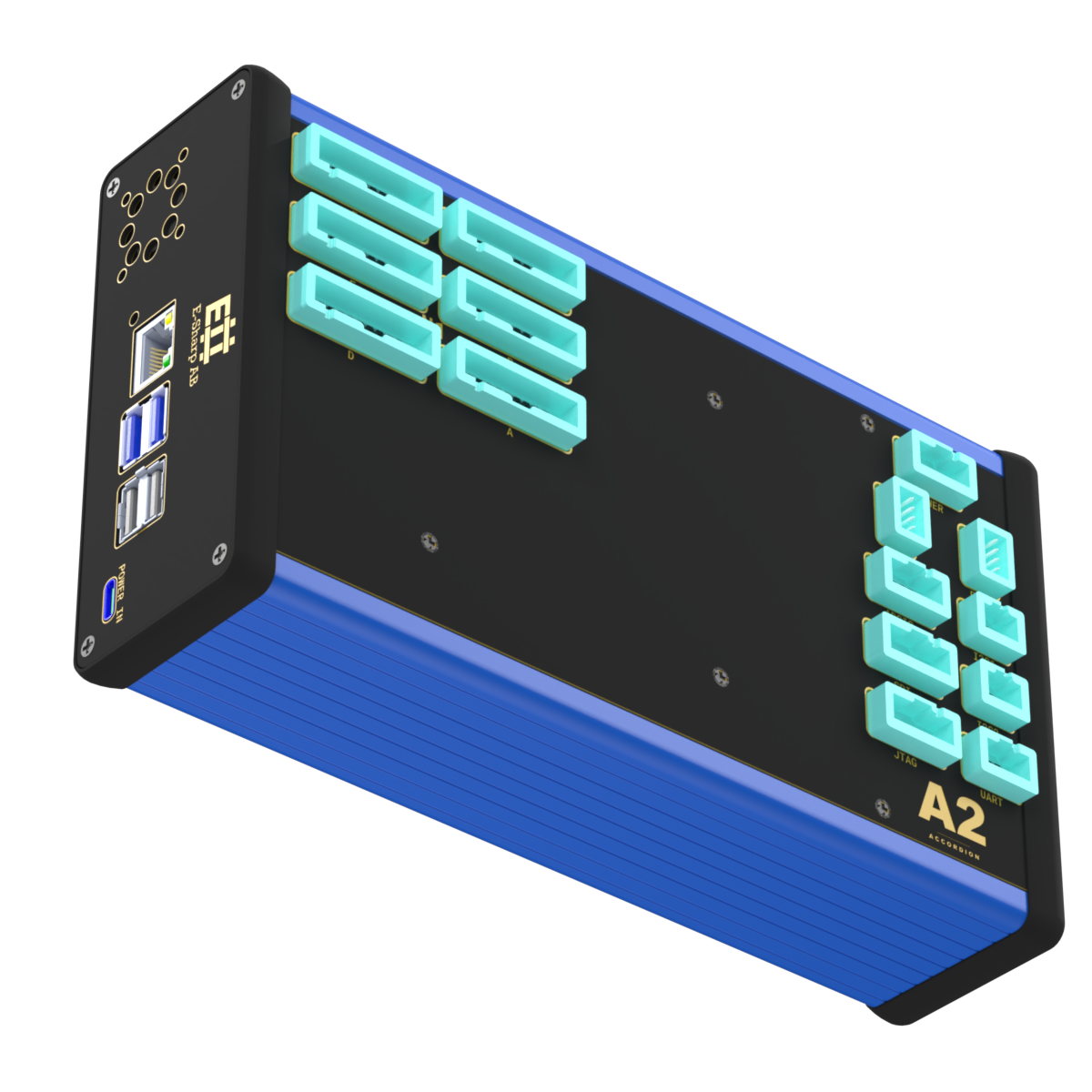
Accordion A2 Plus
A fully loaded Accordion A2 — measure, power, talk to and monitor your DUT from a single networked node.
- 96 mixed-signal channels (MPIO-96) for analogue in/out and pseudo-digital I/O
- 2-channel programmable PSU, 0–20 V / 0–10 A, 60 W, with PMBus telemetry
- I²C, UART, SPI, JTAG, fan control and RGB status in the communication module
- Networked — controlled from the Web API, Pilot, Shell, Python, .NET or TestStand
- Lifetime licences for Accordion Pilot and Shell included
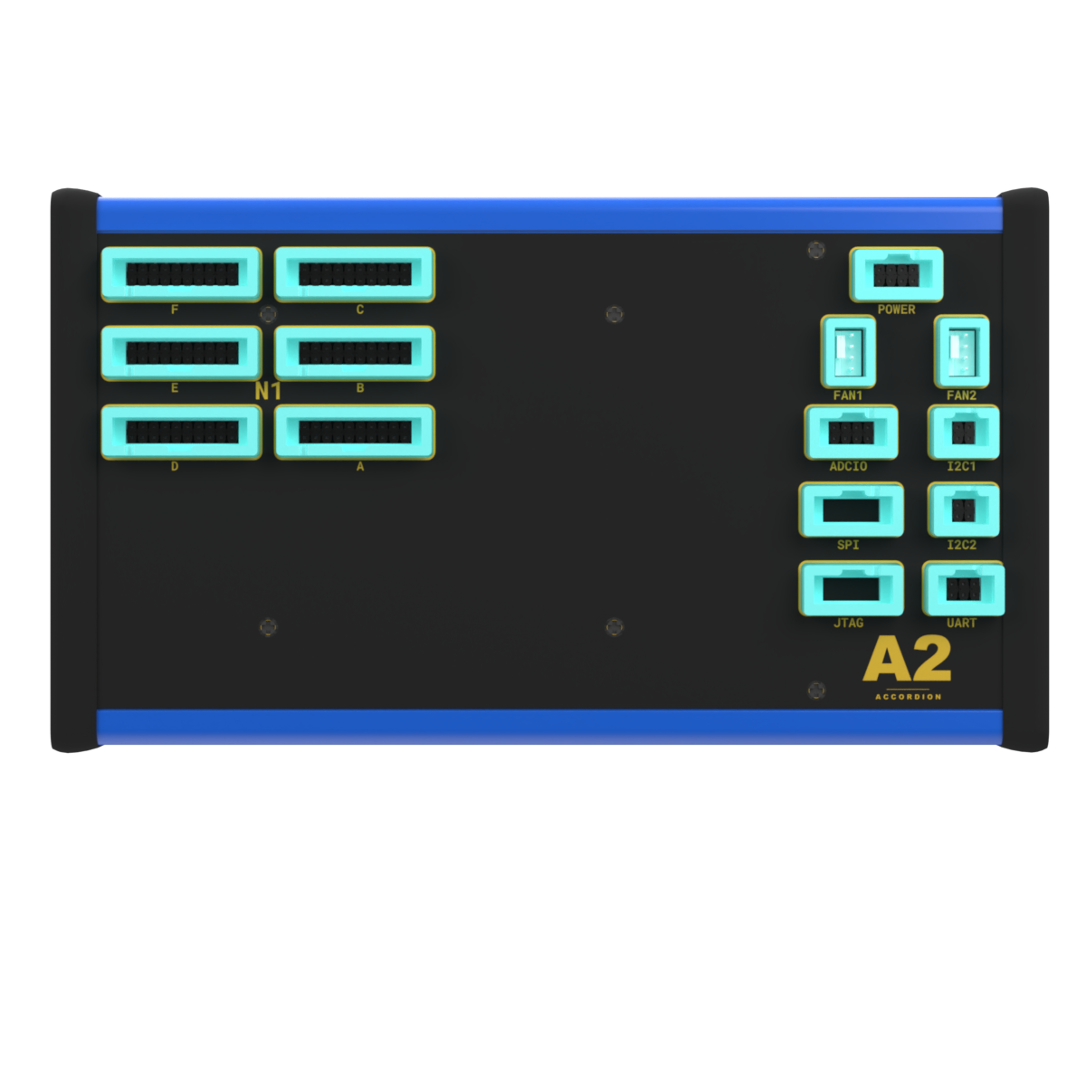
Accordion A2 Plus is a fully loaded configuration of the Accordion A2 test platform, delivered as a ready-made bundle for PCBA test, NPI and production test where you need both mixed-signal channels and programmable power and protocol communication on the same node. The chassis is pre-assembled with four modules — MPIO-96, the 6× IDC N-TOP breakout, the M.2 PSU and the communication module — so a single networked unit can measure, power, exercise and monitor your DUT without you assembling the configuration from individual modules.
Modules in the configuration
This comes pre-assembled in Accordion A2 Plus — click for the datasheet, specifications and connections.
Specifications, connections & manual
All technical material on the page — expand a section, or download the whole datasheet as a PDF.
Specifications
System
| Parameter | Value | Notes |
|---|---|---|
| Product name | Accordion A2 Plus | |
| Part number | ESH10000599 | |
| Platform | Accordion A2 | |
| Power input | USB-C (USB-PD), via bundled 130 W power supply | Use bundled supply only. |
| Power consumption, typical | < 5 W | At idle, all channels INPUT, PSU outputs disabled. |
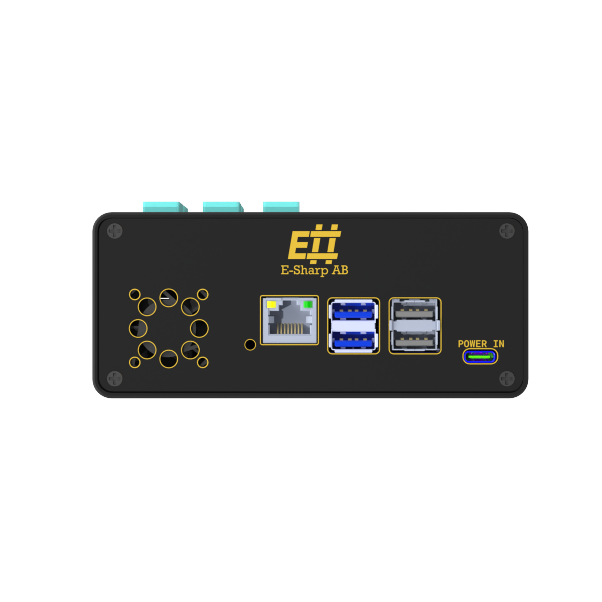
| Network interface | 1× RJ45, 10/100/1000 Mbit/s | Back panel. |
| Auxiliary host ports | 2× USB-A 2.0, 2× USB-A 3.0 | Back panel. |
| M.2 slots | 2, on the front panel (M1, M2) | M1 populated by the PSU module; M2 free. |
| Module slots populated | SO-DIMM T1 (MPIO-96), N-TOP N1 (IDC breakout), dedicated communication TOP, front-panel M.2 M1 (PSU) | |
| Module slots free | 3× SO-DIMM (T2, T3, A1), 3× N-TOP (N2, N3, N4), 1× M.2 (M2) | For future expansion. |
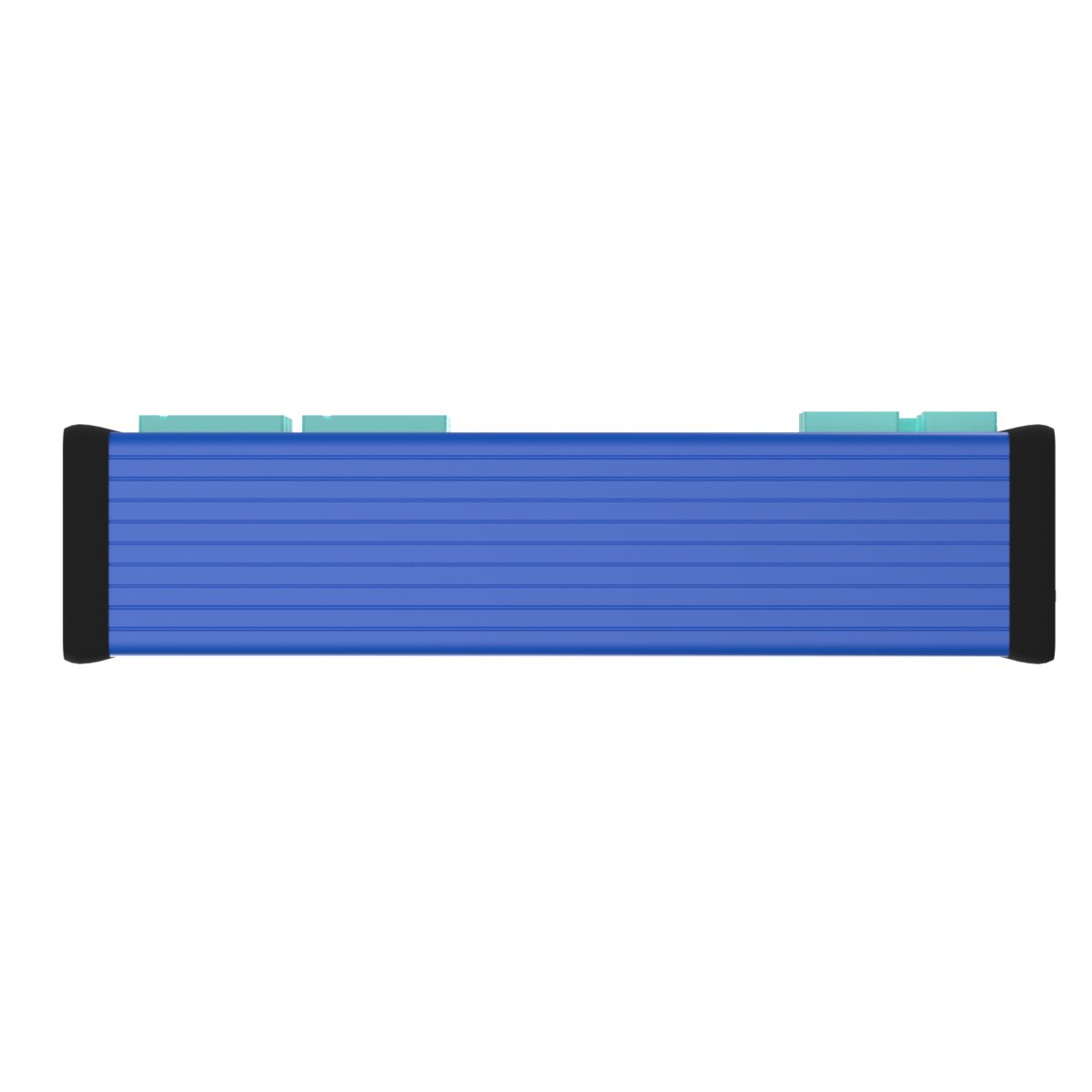
| Dimensions (W × D × H) | 233 × 129 × 60 mm | |
| Weight | 1.08 kg | |
| Compliance | CE, RoHS, REACH |
Included hardware
| Item | Qty | Notes |
|---|---|---|
| Accordion A2 unit | 1 | Pre-configured with the modules below. |
| ESH10000568 — MPIO-96 SPI Module | 1 | 96 reconfigurable channels, AD5592R-based. SO-DIMM slot T1. |
| ESH10000355 — 6× IDC N-TOP Breakout Module | 1 | 96-signal breakout to 6× IDC 20-pin. N-TOP slot N1. |
| ESH10000533 — M.2 PSU Module | 1 | Dual programmable supply, 60 W total. Front-panel M.2 slot M1. |
| ESH10000359 — Communication Module | 1 | I²C / UART / SPI / JTAG, fan control, RGB status LEDs. |
| USB-C power supply | 1 | 130 W, USB-PD. |
| USB-C power cable | 1 | 1 m. |
Included software licenses (lifetime)
| Product | License | Notes |
|---|---|---|
| Accordion Shell | Lifetime, single-unit | CLI tool. dotnet tool install -g AccordionQ2.Shell. |
| Accordion Pilot | Lifetime, single-unit | Windows GUI. |
The Web API, the Python package accordionq2, and the .NET client AccordionQ2.WebApiClient are open clients and are usable without separate licensing.
Channel summary
MPIO-96 (ESH10000568)
| Parameter | Value |
|---|---|
| User channels | 96, bidirectional |
| Modes per channel | Analog input, analog output, pseudo-digital I/O |
| ADC / DAC resolution | 12-bit / 12-bit |
| Analog range | 0–5 V typical (AD5592R 2× mode) |
| High-speed acquisition | Supported, exposed via NumericResult |
| Max voltage / current at IDC pin | 5 V / 2 A |
| ESD on IDC connectors | IEC 61000-4-2, ±30 kV contact, ±30 kV air |
M.2 PSU (ESH10000533)
| Parameter | Value |
|---|---|
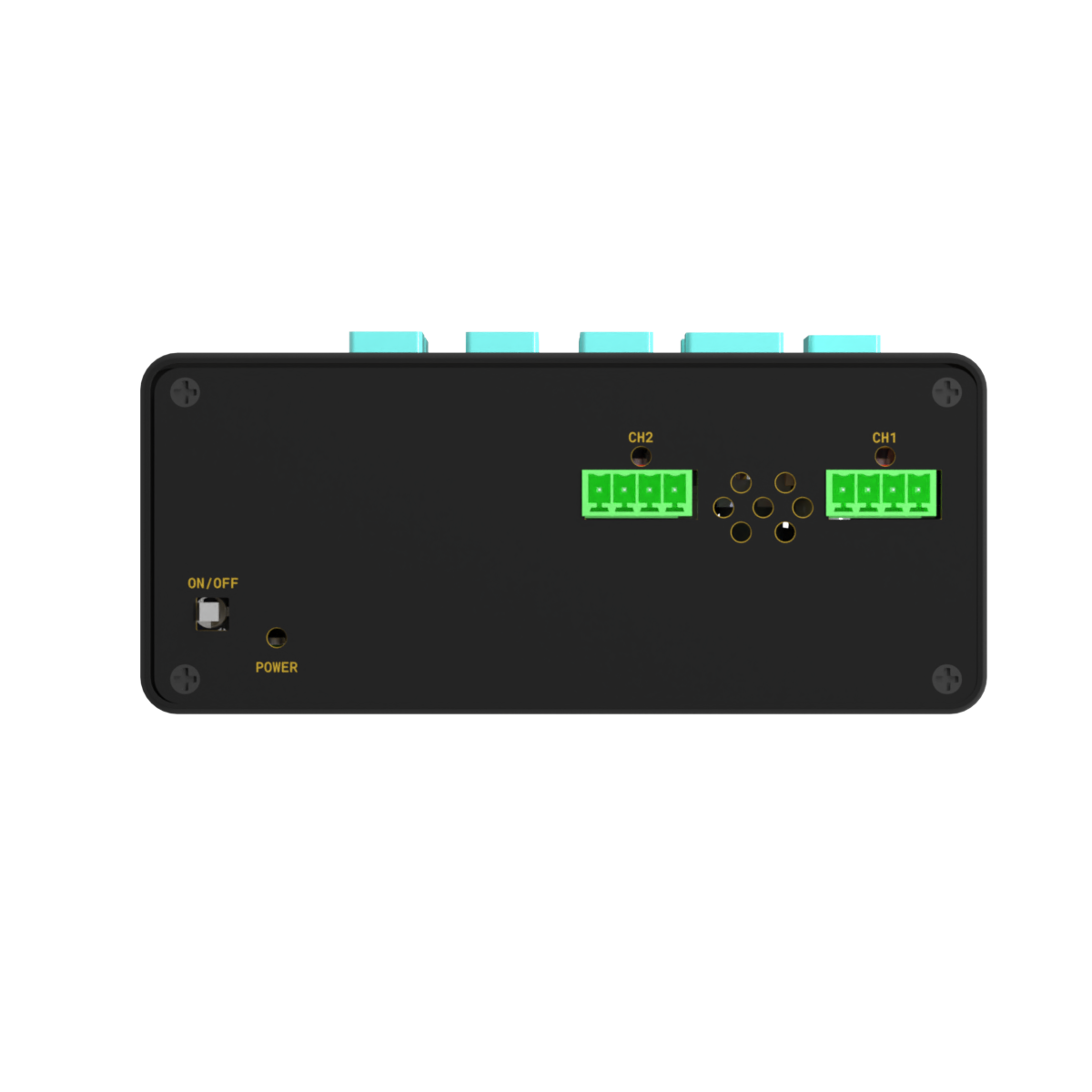
| Channels | 2, independent (CH1, CH2) |
| Output voltage | 0–20 V |
| Output current | 0–10 A |
| Maximum total output power | 60 W (derated, summed across both channels) |
| Controller | Linear Technology LTC3889 (PMBus) |
| Telemetry | READ_VOUT, READ_IOUT, READ_POUT, READ_VIN, READ_IIN, READ_TEMPERATURE_1/2 |
Communication module (ESH10000359)
| Parameter | Value |
|---|---|
| Communication interfaces | 2× I²C, UART (RS232), SPI, JTAG |
| Analog channels | 4× VOUT (output-only), 4× MPIO (bidirectional) |
| Fan control | 2× PWM with tachometer feedback (MAX6650) |
| Status LEDs | 8× RGB (I2C1, I2C2, UART, SPI, JTAG, POWER, FAN, ADCIO) |
| Always-on chassis power rails | 20 V, 12 V, 5 V, 3.3 V; each thermal-fused at 0.5 A |
Constraints
- 96 user signals on the IDC connectors are routed 1:1 from the MPIO-96 — no conditioning, no multiplexing.
- PSU module: 60 W total across both channels (derated from per-channel maximum).
- IDC connectors: 5 V max, 2 A max per signal pin; +5 V and +12–20 V rails are thermistor-fused at 0.25 A.
- USB-C powered. The bundled 130 W USB-PD supply is the only supported supply.
Connections (pinout)
Back-panel chassis connectors
| Designator | Type | Direction | Description | Notes |
|---|---|---|---|---|
| NET | RJ45 | Bidirectional | Ethernet to control network | 10/100/1000 Mbit/s. |
| POWER | USB-C | Power input | 5–20 V (USB-PD) from bundled supply | Use bundled 130 W supply only. |
| USB1–USB4 | USB-A | Bidirectional | Auxiliary host ports | 2× USB-A 2.0 + 2× USB-A 3.0. |
Front-panel M.2 PSU module — output connectors (J2, J3)
| Pin | Signal (CH1 / CH2) | Direction | Description |
|---|---|---|---|
| J2_1 / J3_1 | VPSU_0 / VPSU_1 | Power out | Settable supply (0–20 V), per-channel. |
| J2_2 / J3_2 | VSENSE+_0 / VSENSE+_1 | Input | Remote sense, positive terminal. |
| J2_3 / J3_3 | VSENSE-_0 / VSENSE-_1 | Input | Remote sense, negative terminal. |
| J2_4 / J3_4 | GND | — | Common ground. |
Top — IDC signal connectors (J1–J6)
Six 20-pin (2×10, 2.54 mm pitch) IDC connectors. Connector → DATA-line mapping (1:1 to MPIO-96 via SO-DIMM slot T1):
| Connector | Signals (DATA[…]) | Mapped MPIO channels |
|---|---|---|
| J1 | DATA[0–15] | MPIO00–MPIO15 |
| J2 | DATA[16–31] | MPIO16–MPIO31 |
| J3 | DATA[32–47] | MPIO32–MPIO47 |
| J4 | DATA[48–63] | MPIO48–MPIO63 |
| J5 | DATA[64–79] | MPIO64–MPIO79 |
| J6 | DATA[80–95] | MPIO80–MPIO95 |
Per-connector fixed pins: pin 1 = +5 V (thermistor-fused 0.25 A), pin 2 = +12–20 V (thermistor-fused 0.25 A), pins 3–20 = 16× DATA + GND returns.
Manual
Power-on procedure
- Connect the USB-C power supply to mains.
- Connect the USB-C cable from the supply to the POWER port on the front of the unit.
- Connect an Ethernet cable from the front-panel RJ45 to the same network as the controlling PC.
- Press the power button on the back of the unit and wait for it to boot.
- The unit is reachable by hostname (printed on the quick start card) or by DHCP-assigned IP.
The chassis power rails (20 V, 12 V, 5 V, 3.3 V) are live at boot and thermal-fused at 0.5 A. The PSU outputs (VPSU_0, VPSU_1) are NOT enabled at boot — they require explicit software enable (OPERATION / OUTPUT_ENABLE per channel).
Channel naming
| Module | Convention | Example |
|---|---|---|
| MPIO-96 (ESH10000568) | {ModuleIndex}.ESH10000568.MPIO{00–95} |
1.ESH10000568.MPIO42 |
| Communication (ESH10000359) | {ModuleIndex}.ESH10000359.{ChannelName} |
15.ESH10000359.I2C1 |
| PSU (ESH10000533) | {ModuleIndex}.ESH10000533.{Address}.{Channel}.{Register} |
0.ESH10000533.0x4F.CH1.VOUT_COMMAND |
Driving the MPIO-96
from accordionq2 import Pilot

pilot = Pilot(host="accordion-a2-plus-XXXX")
pilot.attach()

# Configure MPIO00 as analog output, drive 2.500 V
ch = pilot.get_channel("1.ESH10000568.MPIO00")
ch.configure(mode="analog_output")
ch.write_analog(2.500)

# Read MPIO01 as analog input
v = pilot.get_channel("1.ESH10000568.MPIO01").read_analog()
Driving the M.2 PSU module
psu_ch1 = pilot.get_channel("0.ESH10000533.0x4F.CH1.VOUT_COMMAND")
psu_ch1.write(3.300)                                    # 3.3 V on CH1

en = pilot.get_channel("0.ESH10000533.0x4F.CH1.OPERATION")
en.write(True)

vout = pilot.get_channel("0.ESH10000533.0x4F.CH1.READ_VOUT").read()
The 60 W ceiling is a total across both PSU channels. Plan combined V × I to stay below 60 W or expect over-power protection to fire.
Application notes, cases & news
Insights tagged for this product.
The right Accordion for your bench?
Tell us what you're testing and we'll find the right configuration — or say honestly if a standard setup is enough.