Communication
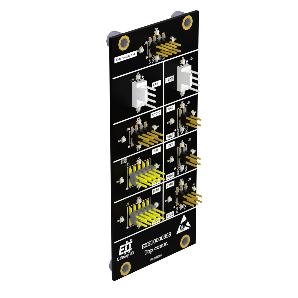
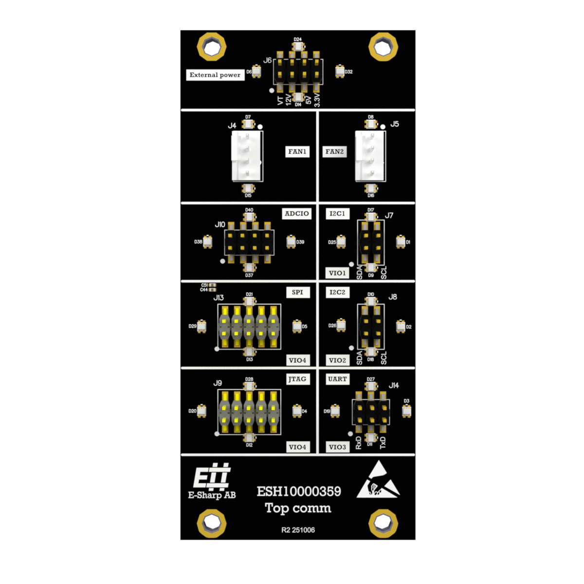
Protocol hub for Accordion — drive and power the DUT-side interfaces, with fan control and status indication.
- 2× I²C, UART (RS232), SPI and JTAG with programmable voltage per bus (0–5 V)
- 4× VOUT and 4× MPIO (analogue/pseudo-digital), 12-bit, 0–5 V
- 2× PWM fan control with speed feedback (MAX6650)
- 8 RGB status LEDs, software-controlled
- Synchronised high-speed numeric acquisition (NumericResult)
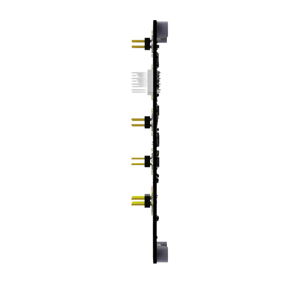
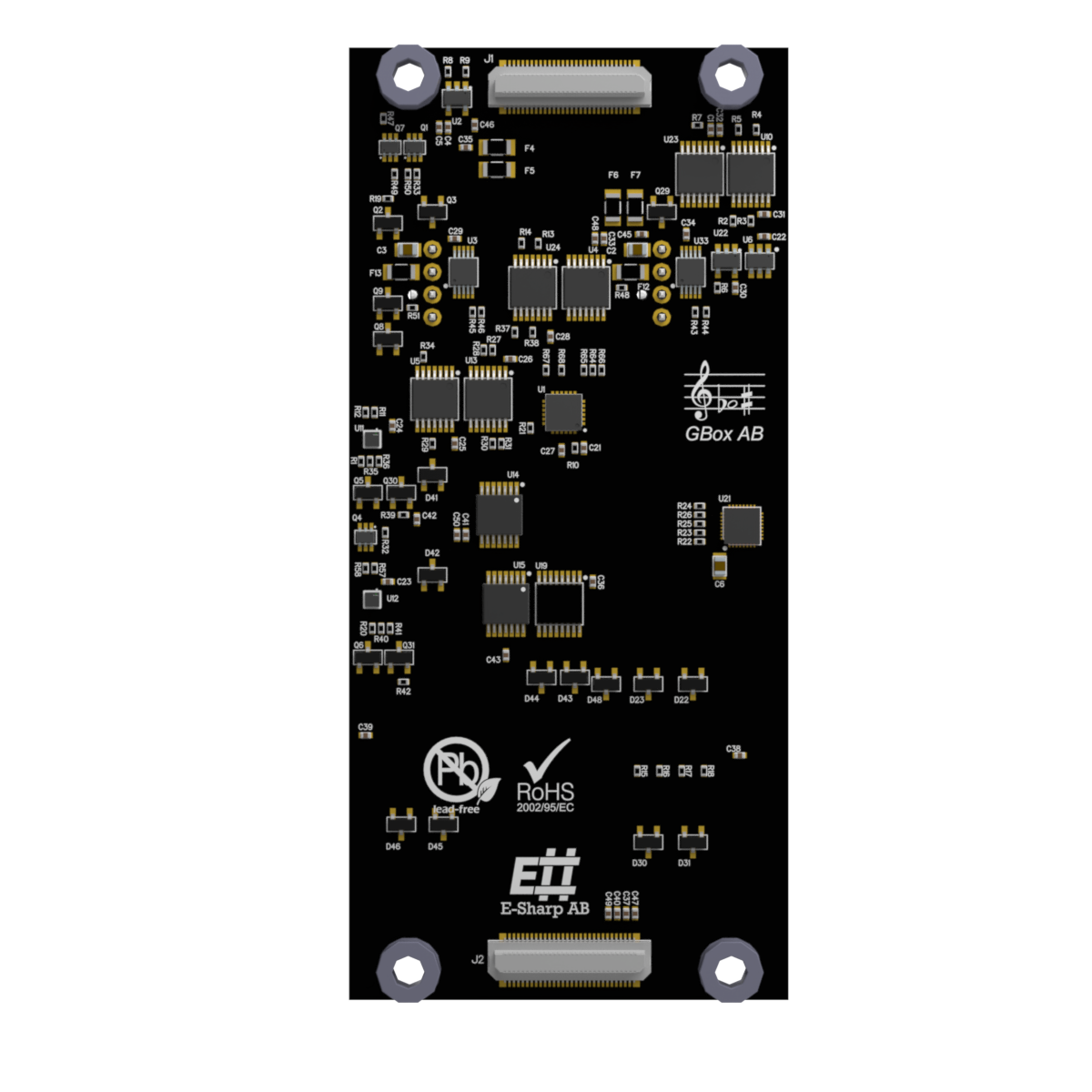
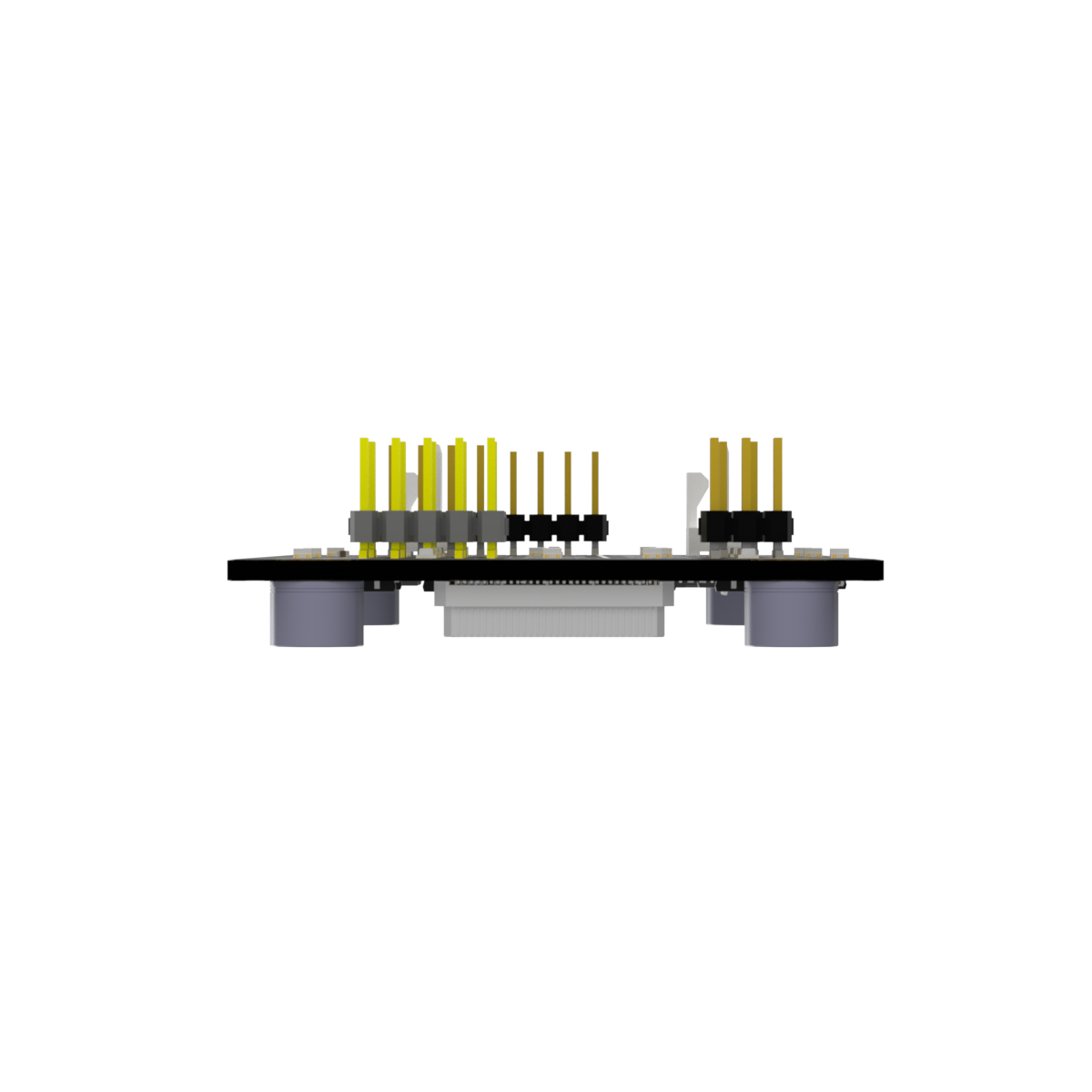
ESH10000359 is the communication and control module for your Accordion — the central coordination point between the host system and the other modules. It provides configurable communication interfaces (I²C, UART, SPI, JTAG), voltage generation for connected buses, analogue/digital I/O, fan control, status indication via RGB LEDs and synchronised numeric data acquisition. The module is fully software-defined and controlled through Accordion's APIs.
Specifications, connections & manual
All technical material on the page — expand a section, or download the whole datasheet as a PDF.
Specifications
| Parameter | Specification |
|---|---|
| Module type | Communication and control (TOP) |
| Communication interfaces | 2× I²C, UART (RS232), SPI, JTAG |
| I²C enable & pull-ups | Per-channel, software-controlled |
| UART default | /dev/serial0, 9600 baud |
| Analogue / DAC resolution | 12-bit |
| Analogue voltage range | 0–5 V |
| Analogue channels | 4× VOUT, 4× MPIO |
| Pseudo-digital support | Yes (MPIO, VL/VH thresholds); open-drain, float |
| Fan control | 2× PWM with tachometer feedback (2× MAX6650) |
| Status LEDs | 8× RGB, software-controlled |
Manual
The module is usually installed as the top module (ModuleIndex = 15). Channels follow {ModuleIndex}.ESH10000359.{ChannelName} — e.g. 15.ESH10000359.I2C1.
I²C — two independent channels, each with enable (I2C1_EN/I2C2_EN), software pull-ups (I2C1_PU/I2C2_PU) and a dedicated voltage output (I2C1_VOUT/I2C2_VOUT). Sequence: set VOUT → enable pull-ups if needed → enable channel → run transactions.
UART — RS232, auto-enabled on access, configurable baud, dedicated UART_VOUT.
SPI and JTAG — share SPI_JTAG_VOUT; each needs an explicit enable (SPI_EN / JTAG_EN).
VOUT channels (output-only, 0–5 V) supply communication buses or DUT rails. MPIO channels are bidirectional (analogue ADC/DAC or pseudo-digital via VL/VH; open-drain VH < 0, float VL < 0).
Fan control — two independent fans, ratiometric speed (0.0–1.0), configurable max RPM, tachometer feedback (FANx, FANx_MAX_RPM, FANx_FREQ).
LED status — eight RGB LEDs (I2C1, I2C2, UART, SPI, JTAG, POWER, FAN, ADCIO), named colours or hex, global luminance.
Numeric acquisition — synchronized multi-channel sampling; results returned base64-encoded via NumericResult.
Pinout
EXT POWER
| Pin | Name | Description |
|---|---|---|
| 1 | 20V | Always on, 0.5 A thermal fuse |
| 3 | 12V | Always on, 0.5 A thermal fuse |
| 5 | 5V | Always on, 0.5 A thermal fuse |
| 7 | 3V3 | Always on, 0.5 A thermal fuse |
| 2, 4, 6, 8 | GND | Ground reference |
I2C [1–2]
| Pin | Name | Description |
|---|---|---|
| 1 | SDA | I²C data; switchable 1 kΩ pull-up to VI2C |
| 2 | VI2C | Programmable I²C power output 0–5 V |
| 3 | SCL | I²C clock; switchable 1 kΩ pull-up to VI2C |
| 4 | GND | Ground reference |
FAN [1–2]
| Pin | Name | Description |
|---|---|---|
| 1 | PWM | PWM output to fan |
| 2 | VFAN | Switchable fan power, 5 V / 12 V |
| 3 | TACH | Tachometer input |
| 4 | N.C | No connect |
SPI
| Pin | Name | Description |
|---|---|---|
| 1 | SCK | SPI clock |
| 3 | CS0 | Chip select 0 |
| 5 | SDI | Serial data in |
| 6 | VSPI/JTAG | Programmable 0–5 V (shared with JTAG) |
| 7 | SDO | Serial data out |
| 9 | CS1 | Chip select 1 |
| 2, 4, 8, 10 | GND | Ground reference |
JTAG
| Pin | Name | Description |
|---|---|---|
| 1 | TCK | Test clock |
| 3 | TMS | Test mode select |
| 5 | TDI | Test data in |
| 6 | VSPI/JTAG | Programmable 0–5 V (shared with SPI) |
| 7 | TDO | Test data out |
| 2, 4, 8 | GND | Ground reference |
| 9, 10 | N.C | No connect |
UART
| Pin | Name | Description |
|---|---|---|
| 1 | RxD | Receive data |
| 2 | VUART | Programmable 0–5 V |
| 3 | RTS | Ready to send |
| 4 | CTS | Clear to send |
| 5 | TxD | Transmit data |
| 6 | GND | Ground reference |
Application notes, cases & news
Insights tagged for this product.
The right Accordion for your bench?
Tell us what you're testing and we'll find the right configuration — or say honestly if a standard setup is enough.