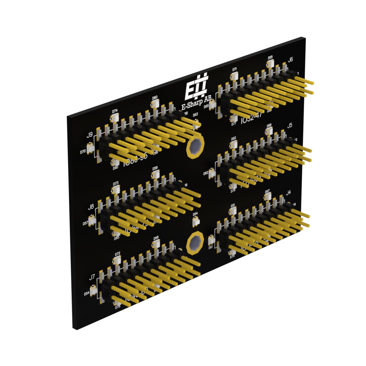
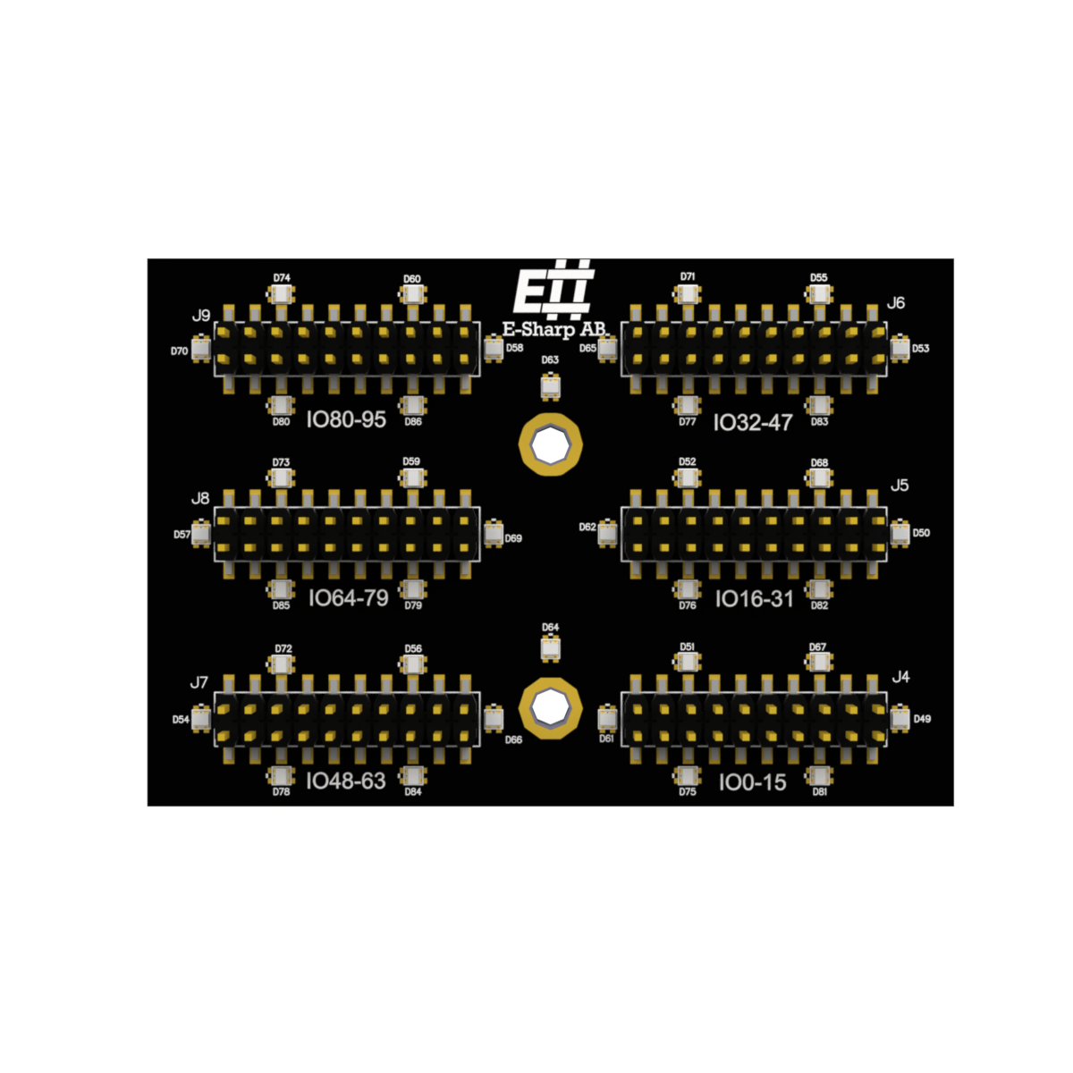
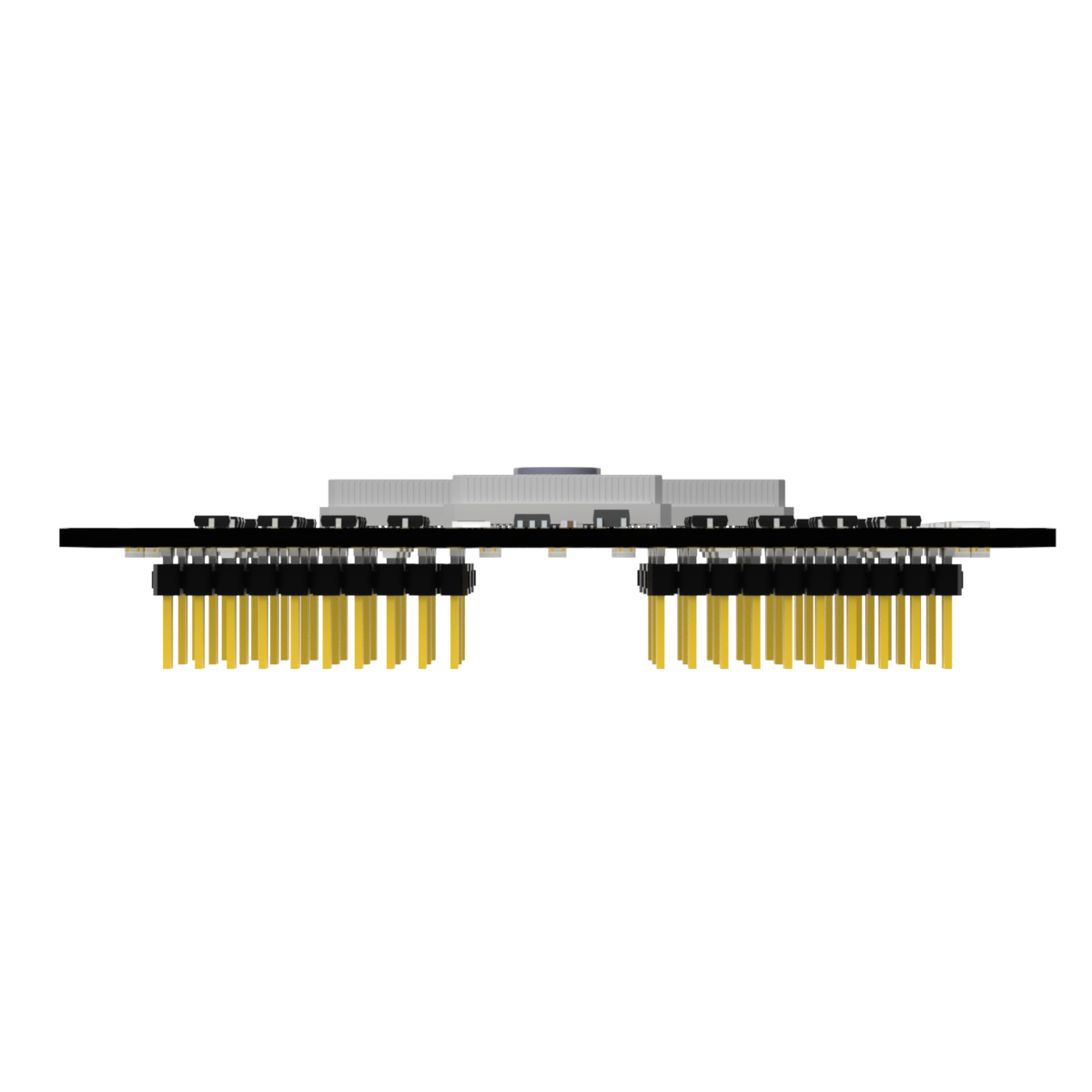
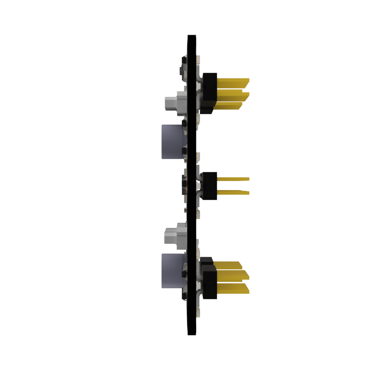
6× IDC N-TOP Breakout
Fast fixture integration — 96 signals 1:1 on six IDC connectors, with no active components.
- 96 user signals (DATA[0–95]) on six 20-pin IDC connectors (J1–J6)
- Direct 1:1 mapping from Accordion's DATA bus — passive, no signal conditioning
- 2.54 mm pitch, standard IDC ribbon cable
- Max 5 V / 2 A per signal pin; ESD IEC 61000-4-2 ±30 kV
- Compatible with Accordion and Accordion A2
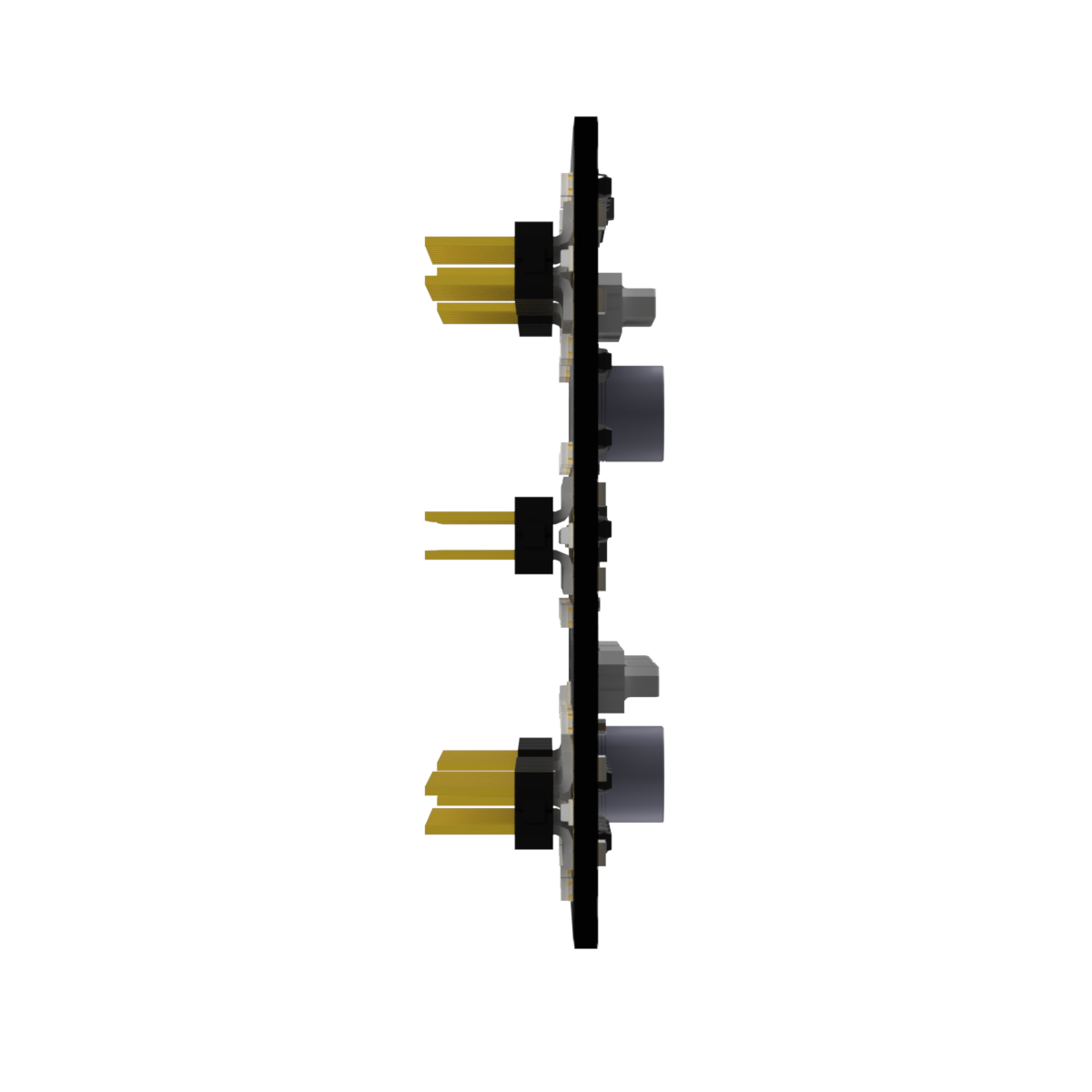
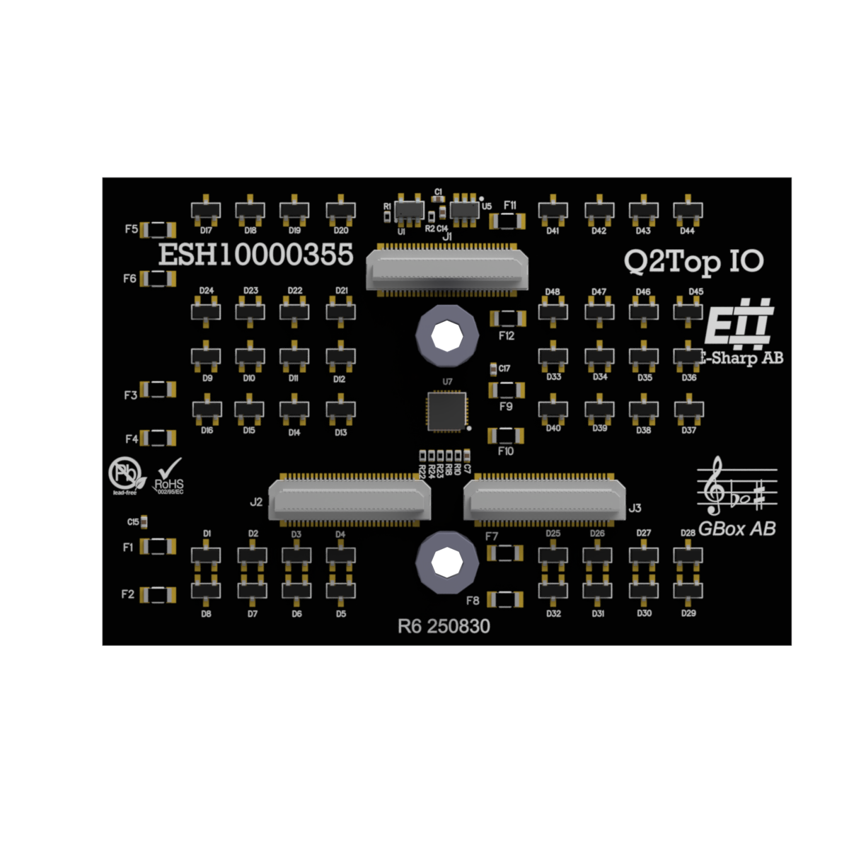
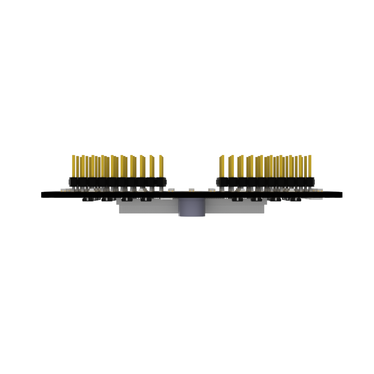
ESH10000355 is an Accordion N-TOP module that breaks out high signal density via six IDC 20-pin connectors, exposing 96 user signals (DATA[0–95]) straight from Accordion's DATA bus. The signals run 1:1 from the system bus to the connectors — no active components, no signal conditioning. Intended for PCBA test, NPI and production test where fast fixture integration and direct signal access are needed.
Specifications, connections & manual
All technical material on the page — expand a section, or download the whole datasheet as a PDF.
Specifications
| Parameter | Value |
|---|---|
| Module type | N-TOP (Accordion) |
| User signals | 96 (DATA[0–95]) |
| Connector type | IDC 20-pin (×6), 2.54 mm pitch |
| Connector designators | J1–J6 |
| Signal mapping | Direct 1:1 to Accordion DATA bus |
| Compatible systems | Accordion, Accordion A2 |
| Max voltage / current | 5 V / 2 A |
| ESD protection | IEC 61000-4-2, ±30 kV contact, ±30 kV air |
Manual
Hardware
Power down the system before inserting or removing modules. Align the module with an available N-TOP slot (N1–N4) — it is keyed, do not force — and press until fully seated. Connect IDC ribbon cables to J1–J6 as required by the fixture.
Slot → SO-DIMM mapping: N1 → T1, N2 → T2, N3 → T3, N4 → A1. The N-TOP slot determines which SO-DIMM connector carries the DATA signals from the top board.
Software
The module is passive — no driver, no configurable parameters. All software interaction is against the source channel (MPIO etc.) routed through the DATA bus; address channels by their logical name via the channel-discovery API.
value = pilot.get_channel("DATA0").read_digital()
pilot.get_channel("DATA0").write_digital(True)
Pinout
Six IDC 20-pin (2×10, 2.54 mm) connectors. Pin 1 is indicated by the chamfer and the marked ribbon wire.
| Connector | DATA lines |
|---|---|
| J1 | DATA[0–15] |
| J2 | DATA[16–31] |
| J3 | DATA[32–47] |
| J4 | DATA[48–63] |
| J5 | DATA[64–79] |
| J6 | DATA[80–95] |
Pin 1 = +5 V (thermistor-fused 0.25 A), pin 2 = +12–20 V (thermistor-fused 0.25 A); the remaining pins carry 16 DATA signals and GND returns.
Application notes, cases & news
Insights tagged for this product.
The right Accordion for your bench?
Tell us what you're testing and we'll find the right configuration — or say honestly if a standard setup is enough.